
Universitas ASA Indonesia
Program Studi: Teknologi Informasi
Mata Kuliah: Internet of Things
SKS: 3 (Tiga)
Dosen Pengampu: Istiqomah Sumadikarta, S.T., M.Kom.
LDR (Light Dependent Resistor) adalah resistor yang nilainya berubah tergantung intensitas cahaya. Semakin terang cahaya, resistansi semakin kecil.
Sinyal analog dari LDR dibaca oleh pin analog Arduino untuk mengetahui intensitas cahaya sekitar. Sensor ini akan meningkat resistansi atau hambatannya apabila cahaya yang diterima sedikit. Sebaliknya, apabila cahaya yang diterima banyak maka resistansinya akan mengecil. Sensor ini dapat dimanfaatkan untuk saklar lampu otomatis.
1. Buatlah rangkaian simulasi LDR di Wokwi seperti berikut ini:

Rangkaian ini menggunakan sensor LDR untuk mendeteksi intensitas cahaya, menyalakan LED saat gelap, dan menampilkan nilai intensitas pada LCD I2C.
| No | Komponen | Fungsi |
|---|---|---|
| 1 | Arduino Uno | Mikrokontroler utama untuk mengatur proses pembacaan sensor dan output |
| 2 | Sensor LDR | Mengukur intensitas cahaya dan menghasilkan sinyal analog |
| 3 | LED Merah | Indikator visual saat kondisi gelap |
| 4 | LCD 1602 (I2C) | Menampilkan nilai cahaya yang dibaca oleh sensor |
| 5 | Resistor 1kΩ | Membatasi arus untuk melindungi LED |
| Komponen | Pin | Ke | Pin Tujuan | Warna Kabel | Fungsi |
|---|---|---|---|---|---|
| LDR | VCC | Arduino Uno | 5V | Merah | Memberi daya ke sensor |
| LDR | GND | Arduino Uno | GND | Hitam | Ground sensor |
| LDR | AO | Arduino Uno | A0 | Oranye | Mengirim data analog |
| LCD1602 | VCC | Arduino Uno | 5V | Merah | Power untuk LCD |
| LCD1602 | GND | Arduino Uno | GND | Hitam | Ground LCD |
| LCD1602 | SDA | Arduino Uno | A4 | Hijau | Data line I2C |
| LCD1602 | SCL | Arduino Uno | A5 | Biru | Clock line I2C |
| LED | Cathode | Arduino Uno | GND | Hitam | Ground LED |
| LED | Anode | Resistor | 1kΩ | Hijau | Input arus LED |
| Resistor | 1kΩ | Arduino Uno | Pin 2 | Hijau | Kontrol nyala LED |
Sensor LDR membaca intensitas cahaya sekitar, nilai ini dikirim ke pin analog A0 pada Arduino. Arduino memproses nilai ini:
Nilai cahaya ditampilkan secara real-time di layar LCD 1602 melalui komunikasi I2C.
2. Buat kode pemrograman seperti berikut ini:
#include
#include
// Inisialisasi LCD dengan alamat I2C dan ukuran 16x2
LiquidCrystal_I2C lcd(0x27, 16, 2);
// Pin untuk LDR dan LED
const int ldrPin = A0;
const int ledPin = 2;
void setup() {
  // Inisialisasi LCD
  lcd.begin(16, 2);
  lcd.backlight(); // Menyalakan lampu latar LCD
  // Inisialisasi serial monitor
  Serial.begin(9600);
  // Inisialisasi pin
  pinMode(ledPin, OUTPUT);
  pinMode(ldrPin, INPUT);
}
void loop() {
  // Membaca nilai dari sensor LDR (0-1023)
  int ldrValue = analogRead(ldrPin);
  // Tampilkan di Serial Monitor
  Serial.print("LDR Value: ");
  Serial.println(ldrValue);
  // Tampilkan di LCD
  lcd.clear();
  lcd.setCursor(0, 0);
  lcd.print("Cahaya: ");
  lcd.setCursor(0, 1);
  lcd.print(ldrValue);
  // Menyalakan LED jika gelap (misal < 500)
  if (ldrValue < 500) {
    digitalWrite(ledPin, HIGH);
  } else {
    digitalWrite(ledPin, LOW);
  }
  delay(1000); // delay 1 detik
}
3. Tambahkan library LiquidCrystal_I2C di Library Manager
4. Jalankan simulator, kemudian rubah intensitas cahaya, perhatikan perubahan pada LED dan LCD.

Rotary encoder, juga disebut shaft encoder, yaitu perangkat elektro-mekanis yang mengubah posisi sudut atau gerakan poros atau gandar menjadi sinyal keluaran analog atau digital. Komponen ini memiliki dua pin keluaran yang menghasilkan sinyal pulsa yang diproses dahulu untuk mendapatkan arah putarannya.
Rotary encoder memiliki 3 pin utama: CLK, DT, dan SW (switch). Sinyal CLK dan DT digunakan membaca arah, sedangkan SW sebagai tombol tekan.
Rotary encoder umum digunakan pada menu navigasi, pemilih volume, dan kontrol gerakan.
1. Buatlah rangkaian Arduino, LiquidCrystal_I2C, Rotary Encoder

| No | Komponen | ID | Catatan |
|---|---|---|---|
| 1 | Arduino Uno | uno |
Pusat kendali mikrokontroler |
| 2 | Rotary Encoder KY-040 | encoder1 |
Memiliki pin CLK, DT, SW untuk input rotasi dan tombol |
| 3 | LCD1602 (I2C) | lcd1 |
Menggunakan komunikasi I2C, hemat pin |
| Pin Encoder | Terhubung ke | Pin Arduino | Warna Kabel | Fungsi |
|---|---|---|---|---|
| CLK | uno:2 | D2 | Hijau | Clock signal (interrupt) |
| DT | uno:3 | D3 | Hijau | Data signal |
| SW | uno:4 | D4 | Hijau | Tombol push |
| VCC | uno:5V | 5V | Merah | Catu daya |
| GND | uno:GND.2 | Ground | Coklat | Ground |
| Pin LCD | Terhubung ke | Pin Arduino | Warna Kabel | Fungsi |
|---|---|---|---|---|
| SCL | uno:A5 | A5 | Hijau | Serial Clock |
| SDA | uno:A4 | A4 | Hijau | Serial Data |
| VCC | uno:5V | 5V | Merah | Catu daya |
| GND | uno:GND.3 | Ground | Hitam | Ground |
Encoder.h (atau bisa menggunakan digitalRead
biasa)LiquidCrystal_I2C.h dengan lcd.begin(16, 2); dan
lcd.backlight();
2. Buat kode pemrograman agar rangkaian dapat bekerja sesuai fungsinya.
#include
#include
#define CLK 2
#define DT 3
#define SW 4
LiquidCrystal_I2C lcd(0x27, 16, 2);
volatile int counter = 0;
int lastCLK = HIGH;
bool lastButtonState = HIGH;
void setup() {
  pinMode(CLK, INPUT);
  pinMode(DT, INPUT);
  pinMode(SW, INPUT_PULLUP);
  lcd.begin(16, 2);
  lcd.backlight();
  lcd.setCursor(0, 0);
  lcd.print("Counter:");
  lcd.setCursor(0, 1);
  lcd.print(counter);
}
void loop() {
  int currentCLK = digitalRead(CLK);
  if (currentCLK != lastCLK && currentCLK == LOW) {
    if (digitalRead(DT) == HIGH) {
      counter++;
    } else {
      counter--;
    }
    lcd.setCursor(0, 1);
    lcd.print("                ");
    lcd.setCursor(0, 1);
    lcd.print(counter);
    delay(2); // debounce sangat kecil
  }
  lastCLK = currentCLK;
  // Reset saat tombol ditekan
  bool currentButtonState = digitalRead(SW);
  if (currentButtonState == LOW && lastButtonState == HIGH) {
    counter = 0;
    lcd.setCursor(0, 1);
    lcd.print("                ");
    lcd.setCursor(0, 1);
    lcd.print(counter);
    delay(300); // debounce tombol
  }
  lastButtonState = currentButtonState;
}
3. Tambahkan library Rotary Encoder pada Library Manager
4. Jalankan simulasi, coba naik dan turunkan nilai Rotary Encoder, atau tekan tombol, amati perubahannya.

OLED (Organic Light-Emitting Diode) adalah komponen yang terbuat dari rantai hidrokarbon untuk memancarkan cahaya ketika kontak dengan listrik. OLED membuat tampilan dengan menyalakan cahaya pada masing- masing pixel sehingga lebih hemat daya. OLED yang banyak digunakan menggunakan komunikasi I2C atau SPI.

OLED ditampilkan berdasarkan pixel. Umumnya ukuran OLED adalah 128x64 atau 128x32. Format penulisan pixel pada program adalah berdasarkan posisi dimulainya karakter yang ingin dituliskan dengan format (posisi x, posisi y) Contoh: (30, 10)

1. Buatlah rangkaian Arduino, Rotary Encoder, OLED, seperti berikut ini:

| Komponen | ID | Keterangan |
|---|---|---|
| Arduino Uno | uno | Mikrokontroler utama untuk membaca input dan mengendalikan output |
| Rotary Encoder (KY-040) | encoder1 | Input perangkat putar + tombol tekan |
| OLED Display SSD1306 | oled1 | Layar tampilan 128x64 pixel menggunakan komunikasi I2C |
| Dari | Ke | Warna Kabel | Fungsi |
|---|---|---|---|
| encoder1:CLK | uno:2 | Orange | Clock signal dari rotary encoder |
| encoder1:DT | uno:3 | Gold | Data signal dari rotary encoder |
| encoder1:SW | uno:4 | Violet | Tombol tekan dari rotary encoder |
| encoder1:VCC | uno:5V | Merah | Sumber daya rotary encoder |
| encoder1:GND | uno:GND.2 | Hitam | Ground rotary encoder |
| oled1:GND | uno:GND.3 | Hitam | Ground OLED |
| oled1:VCC | uno:5V | Merah | Sumber daya OLED |
| oled1:SCL | uno:A5 | Orange | Clock I2C untuk OLED |
| oled1:SDA | uno:A4 | Biru | Data I2C untuk OLED |
Adafruit_SSD1306 dan Adafruit_GFX versi yang tepat (yang
mendukung parameter (width, height, &Wire, -1)).0x3C adalah default untuk SSD1306 dan cocok dengan koneksi ini.Buat kode pemrograman agar rangkaian dapat berfungsi seperti berikut:
#include
#include
#include
// OLED config
#define SCREEN_WIDTH 128
#define SCREEN_HEIGHT 64
Adafruit_SSD1306 display(SCREEN_WIDTH, SCREEN_HEIGHT, &Wire);
// Rotary encoder pins
const int pinCLK = 2;
const int pinDT = 3;
const int pinSW = 4;
int counter = 0;
int lastCLKState;
bool lastButtonState = HIGH;
void setup() {
  Serial.begin(9600);
  pinMode(pinCLK, INPUT);
  pinMode(pinDT, INPUT);
  pinMode(pinSW, INPUT_PULLUP);
  lastCLKState = digitalRead(pinCLK);
  // Inisialisasi OLED
  if (!display.begin(SSD1306_SWITCHCAPVCC, 0x3C)) {
    Serial.println(F("OLED tidak ditemukan"));
    while (true);
  }
  display.clearDisplay();
  display.setTextSize(2);
  display.setTextColor(SSD1306_WHITE);
  tampilkanCounter();
}
void loop() {
  int currentCLK = digitalRead(pinCLK);
  if (lastCLKState == LOW && currentCLK == HIGH) {
    if (digitalRead(pinDT) == LOW) {
      counter++;
    } else {
      counter--;
    }
    tampilkanCounter();
  }
  lastCLKState = currentCLK;
  bool buttonState = digitalRead(pinSW);
  if (buttonState == LOW && lastButtonState == HIGH) {
    counter = 0;
    tampilkanCounter();
    delay(300);
  }
  lastButtonState = buttonState;
}
void tampilkanCounter() {
  display.clearDisplay();
  display.setCursor(0, 20);
  display.print("Nilai:");
  display.setCursor(0, 45);
  display.print(counter);
  display.display();
}
3. Tambahkan library: CF Rotary Encoder, Adafruit GFX Library, Adafruit SSD1306 di Library Manager
4. Jalankan Simulator, coba putar kiri, kanan, dan tekan pada Rotary Encoder, perhatikan hasilnya.

Gyroscope adalah alat sensor yang dipakai untuk melacak rotasi atau perputaran suatu perangkat berdasarkan gerakan. Dengan kata lain gyroscope juga disebut sebagai perangkat yang dipakai untuk mempertahankan orientasi dari sebuah sudut agar tetap stabil. Saat ini gyroscope banyak digunakan terutama pada smartphone sehingga kita bisa mengatur orientasi layar, bermain game, dll.
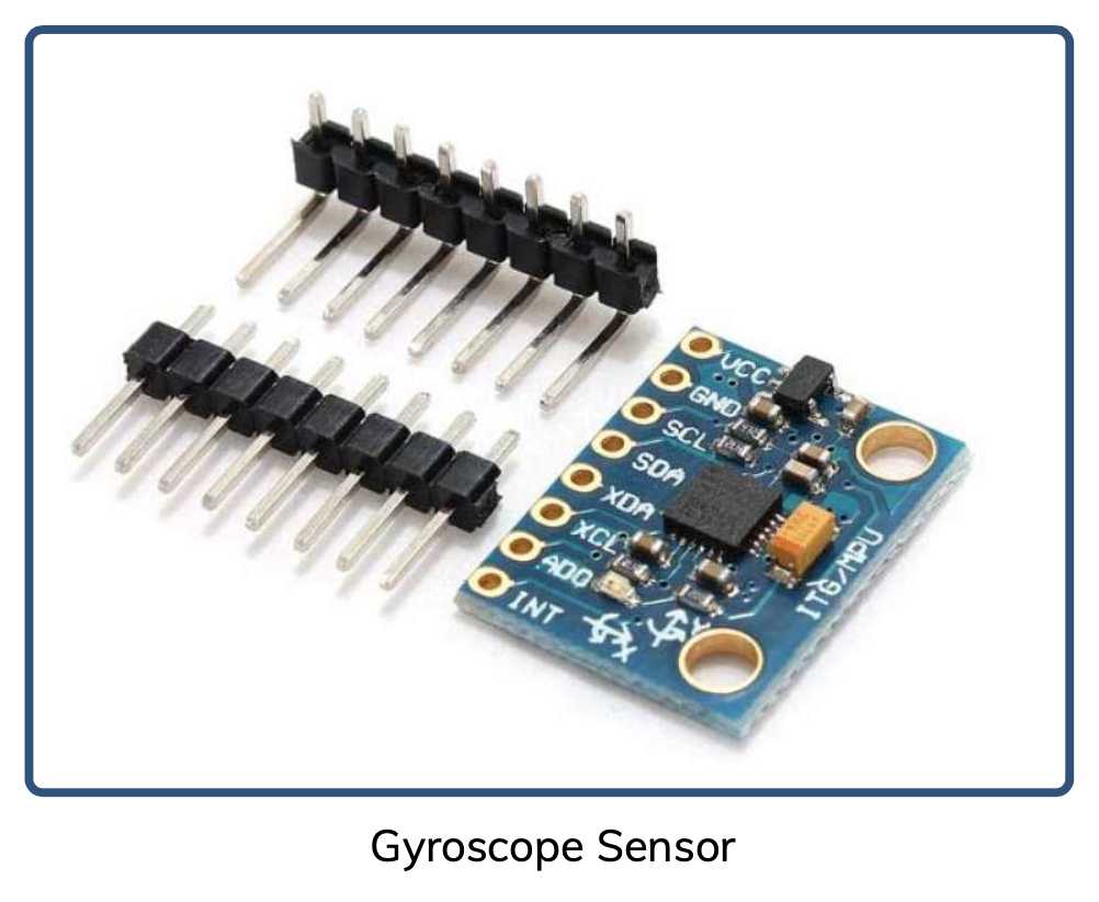
MEMS (Micro-Electro-Mechanical Systems) memungkinkan sensor gyroscope dikemas kecil dan digunakan pada banyak perangkat.

1. Buat rangkaian Arduino dan Gyroscope seperti berikut ini

Proyek ini bertujuan untuk membaca dan menampilkan data sensor dari MPU6050 secara real-time, meliputi:
| Komponen | Fungsi |
|---|---|
| Arduino Uno | Mikrokontroler utama untuk membaca dan mengolah data |
| MPU6050 | Sensor IMU yang berisi akselerometer, gyroscope, dan sensor suhu |
| Kabel Jumper | Menghubungkan modul sensor ke board Arduino |
| Serial Monitor | Menampilkan data pembacaan sensor secara real-time |
2. Buat kode program
#include
#include
#include
Adafruit_MPU6050 mpu;
void setup(void) {
  Serial.begin(115200);
  while (!Serial)
    delay(10); // will pause Zero, Leonardo, etc until serial console opens
  Serial.println("Adafruit MPU6050 test!");
  // Try to initialize!
  if (!mpu.begin()) {
    Serial.println("Failed to find MPU6050 chip");
    while (1) {
      delay(10);
    }
  }
  Serial.println("MPU6050 Found!");
  mpu.setAccelerometerRange(MPU6050_RANGE_8_G);
  Serial.print("Accelerometer range set to: ");
  switch (mpu.getAccelerometerRange()) {
  case MPU6050_RANGE_2_G:
    Serial.println("+-2G");
    break;
  case MPU6050_RANGE_4_G:
    Serial.println("+-4G");
    break;
  case MPU6050_RANGE_8_G:
    Serial.println("+-8G");
    break;
  case MPU6050_RANGE_16_G:
    Serial.println("+-16G");
    break;
  }
  mpu.setGyroRange(MPU6050_RANGE_2000_DEG);
  Serial.print("Gyro range set to: ");
  switch (mpu.getGyroRange()) {
  case MPU6050_RANGE_250_DEG:
    Serial.println("+- 250 deg/s");
    break;
  case MPU6050_RANGE_500_DEG:
    Serial.println("+- 500 deg/s");
    break;
  case MPU6050_RANGE_1000_DEG:
    Serial.println("+- 1000 deg/s");
    break;
  case MPU6050_RANGE_2000_DEG:
    Serial.println("+- 2000 deg/s");
    break;
  }
  mpu.setFilterBandwidth(MPU6050_BAND_21_HZ);
  Serial.print("Filter bandwidth set to: ");
  switch (mpu.getFilterBandwidth()) {
  case MPU6050_BAND_260_HZ:
    Serial.println("260 Hz");
    break;
  case MPU6050_BAND_184_HZ:
    Serial.println("184 Hz");
    break;
  case MPU6050_BAND_94_HZ:
    Serial.println("94 Hz");
    break;
  case MPU6050_BAND_44_HZ:
    Serial.println("44 Hz");
    break;
  case MPU6050_BAND_21_HZ:
    Serial.println("21 Hz");
    break;
  case MPU6050_BAND_10_HZ:
    Serial.println("10 Hz");
    break;
  case MPU6050_BAND_5_HZ:
    Serial.println("5 Hz");
    break;
  }
  Serial.println("");
  delay(100);
}
void loop() {
  /* Get new sensor events with the readings */
  sensors_event_t a, g, temp;
  mpu.getEvent(&a, &g, &temp);
  /* Print out the values */
  Serial.print("Acceleration X: ");
  Serial.print(a.acceleration.x);
  Serial.print(", Y: ");
  Serial.print(a.acceleration.y);
  Serial.print(", Z: ");
  Serial.print(a.acceleration.z);
  Serial.println(" m/s^2");
  Serial.print("Rotation X: ");
  Serial.print(g.gyro.x);
  Serial.print(", Y: ");
  Serial.print(g.gyro.y);
  Serial.print(", Z: ");
  Serial.print(g.gyro.z);
  Serial.println(" rad/s");
  Serial.print("Temperature: ");
  Serial.print(temp.temperature);
  Serial.println(" degC");
  Serial.println("");
  delay(500);
}
3. Tambahkan library Adafruit_MPU6050 di Library Manager
4. Jalankan simulator, rubahlah parameter gyroscope

1. Tambahkan OLED seperti berikut ini:

2. Instruksi tantangan:
Rangkaian ini bertujuan untuk membaca data percepatan dan rotasi dari sensor MPU6050, lalu menampilkannya secara real-time di OLED Display SSD1306. Semua komponen terhubung ke Arduino Uno melalui protokol komunikasi I2C.
| Komponen | Pin | Terhubung ke | Warna Kabel |
|---|---|---|---|
| MPU6050 | VCC | Arduino 5V | Merah |
| MPU6050 | GND | Arduino GND | Hitam |
| MPU6050 | SCL | Arduino A5 | Oranye |
| MPU6050 | SDA | Arduino A4 | Hijau Muda |
| OLED SSD1306 | VCC | Arduino 5V | Merah |
| OLED SSD1306 | GND | Arduino GND | Hitam |
| OLED SSD1306 | SCL | Arduino A5 | Hijau |
| OLED SSD1306 | SDA | Arduino A4 | Hijau |
Pastikan di sisi kode kamu menggunakan library yang sesuai dan inisialisasi OLED dengan alamat 0x3C
(default untuk sebagian besar modul OLED SSD1306).
Kode program untuk diskusi:
#include
#include
#include
#include


Adafruit_SSD1306 display( 128, 64);   // 128 pixels width, 64 pixels height


#define LED_PIN   6
#define LED_COUNT 1
Adafruit_NeoPixel neoPixel( LED_COUNT, LED_PIN, NEO_GRB + NEO_KHZ800);


const int mpuAddress = 0x68;          // I2C address of the MPU-6050


float xByGyro, yByGyro, zByGyro;      // Global variables for the rotation by gyro


// Set the origin in the middle of the display
const int xOrigin = 64;
const int yOrigin = 32;


const float viewDistance = 150.0;     // higher for less perspective, lower for more.


// Vertices for a cube
// A cube has 8 corners and each coordinate has x,y,z values.
#define NUM_VERTICES 8
const int cube_vertex[NUM_VERTICES][3] =
{
  { -20, -20,  20 },     // x, y, z
  {  20, -20,  20 },
  {  20,  20,  20 },
  { -20,  20,  20 },
  { -20, -20, -20 },
  {  20, -20, -20 },
  {  20,  20, -20 },
  { -20,  20, -20 }
};


// The wirefram is to display the lines on the OLED display
// It contains the corners of the shape in 2D coordinates
int wireframe[NUM_VERTICES][2];


void setup()
{
  Serial.begin( 115200);


  Wire.begin();


  // Initialize the OLED display and test if it is connected.
  if( !display.begin( SSD1306_SWITCHCAPVCC, 0x3C))
  {
    Serial.println(F( "SSD1306 allocation failed"));
    for(;;);                                   // halt the sketch if error encountered
  }


  // Initialize the MPU-6050 and test if it is connected.
  Wire.beginTransmission( mpuAddress);
  Wire.write( 0x6B);                           // PWR_MGMT_1 register
  Wire.write( 0);                              // set to zero (wakes up the MPU-6050)
  auto error = Wire.endTransmission();
  if( error != 0)
  {
    Serial.println(F( "Error, MPU-6050 not found"));
    for(;;);                                   // halt the sketch if error encountered
  }


  // Initialize the NeoPixel
  neoPixel.begin();
}


void loop()
{
  Wire.beginTransmission( mpuAddress);
  Wire.write( 0x3B);                   // Starting with register 0x3B (ACCEL_XOUT_H)
  Wire.endTransmission( false);        // No stop condition for a repeated start


  // The MPU-6050 has the values as signed 16-bit integers.
  // There are 7 values in 14 registers.
  int16_t AcX, AcY, AcZ, Tmp, GyX, GyY, GyZ;


  Wire.requestFrom( mpuAddress, 14);   // request a total of 14 bytes
  AcX = Wire.read()<<8 | Wire.read();  // 0x3B (ACCEL_XOUT_H) & 0x3C (ACCEL_XOUT_L)
  AcY = Wire.read()<<8 | Wire.read();  // 0x3D (ACCEL_YOUT_H) & 0x3E (ACCEL_YOUT_L)
  AcZ = Wire.read()<<8 | Wire.read();  // 0x3F (ACCEL_ZOUT_H) & 0x40 (ACCEL_ZOUT_L)
  Tmp = Wire.read()<<8 | Wire.read();  // 0x41 (TEMP_OUT_H)   & 0x42 (TEMP_OUT_L)
  GyX = Wire.read()<<8 | Wire.read();  // 0x43 (GYRO_XOUT_H)  & 0x44 (GYRO_XOUT_L)
  GyY = Wire.read()<<8 | Wire.read();  // 0x45 (GYRO_YOUT_H)  & 0x46 (GYRO_YOUT_L)
  GyZ = Wire.read()<<8 | Wire.read();  // 0x47 (GYRO_ZOUT_H)  & 0x48 (GYRO_ZOUT_L)


  // The acceleration is directly mapped into the angles.
  // That is rather artificial.
  // The combined gravity could be used for an angle, while ignoring the strength.
  //
  // The gyro sets the rotation speed.
  // The angle created by the rotation speed is added to angle by the accelerometer.
  //
  // The conversion from the sensor values to the rotation is just a value
  // that makes it look good on the display.


  float xByAccel = (float) AcX * 0.0001;      // static angle by accelerometer
  float yByAccel = (float) AcY * 0.0001;
  float zByAccel = (float) AcZ * 0.0001;


  xByGyro += (float) GyX * 0.00001;           // moving angle by gyro
  yByGyro += (float) GyY * 0.00001;
  zByGyro += (float) GyZ * 0.00001;


  float x = xByAccel + xByGyro;               // combine both angles
  float y = yByAccel + yByGyro;
  float z = zByAccel + zByGyro;


  // Keep the radians in range (although the cos/sin functions accept every value)
  if( x < 0.0)
    x += 2.0 * M_PI;
  else if( x > 2.0 * M_PI)
    x -= 2.0 * M_PI;
  if( y < 0.0)
    y += 2.0 * M_PI;
  else if( y > 2.0 * M_PI)
    y -= 2.0 * M_PI;
  if( z < 0.0)
    z += 2.0 * M_PI;
  else if( z > 2.0 * M_PI)
    z -= 2.0 * M_PI;


  // Draw 3D picture
  for (int i = 0; i < NUM_VERTICES; i++)
  {
    // Rotate Y
    float rotx = cube_vertex[i][2] * sin(y) + cube_vertex[i][0] * cos(y);
    float roty = cube_vertex[i][1];
    float rotz = cube_vertex[i][2] * cos(y) - cube_vertex[i][0] * sin(y);


    // Rotate X
    float rotxx = rotx;
    float rotyy = roty * cos(x) - rotz * sin(x);
    float rotzz = roty * sin(x) + rotz * cos(x);


    // Rotate Z
    float rotxxx = rotxx * cos(z) - rotyy * sin(z);
    float rotyyy = rotxx * sin(z) + rotyy * cos(z);
    float rotzzz = rotzz;


    // Add depth perspective
    rotxxx *= viewDistance / (viewDistance + rotzzz);
    rotyyy *= viewDistance / (viewDistance + rotzzz);


    // Bring to middle of screen
    rotxxx += (float) xOrigin;
    rotyyy += (float) yOrigin;


    // Store new vertices values for wireframe drawing
    wireframe[i][0] = (int) rotxxx;
    wireframe[i][1] = (int) rotyyy;
    wireframe[i][2] = (int) rotzzz;
  }
  draw_wireframe();


  // Set the color of the NeoPixel according to the temperature
  // Temperature by the MPU-6050 is -40 to 85.
  // According to the datasheet:
  //   Temperature in Celsius = (raw_value / 340) + 36.53
  // The Hue range for the NeoPixel is the full uint16_t range.
  float Celsius = ((float) Tmp / 340.00) + 36.53;
  float hue = (Celsius + 40.0) / 125.0 * 65535.0;
  uint32_t rgbcolor = neoPixel.ColorHSV( (uint16_t) hue);
  neoPixel.setPixelColor( 0, rgbcolor);
  neoPixel.show();                        // update new values to NeoPixel
}


void draw_wireframe(void)
{
  // Start with a empty buffer
  display.clearDisplay();


  // A cube has 8 points and 12 sides.
  // The wireframe contains the 8 points, and the 12 lines are drawn here.
  display.drawLine( wireframe[0][0], wireframe[0][1], wireframe[1][0], wireframe[1][1], SSD1306_WHITE);
  display.drawLine( wireframe[1][0], wireframe[1][1], wireframe[2][0], wireframe[2][1], SSD1306_WHITE);
  display.drawLine( wireframe[2][0], wireframe[2][1], wireframe[3][0], wireframe[3][1], SSD1306_WHITE);
  display.drawLine( wireframe[3][0], wireframe[3][1], wireframe[0][0], wireframe[0][1], SSD1306_WHITE);


  display.drawLine( wireframe[4][0], wireframe[4][1], wireframe[5][0], wireframe[5][1], SSD1306_WHITE);
  display.drawLine( wireframe[5][0], wireframe[5][1], wireframe[6][0], wireframe[6][1], SSD1306_WHITE);
  display.drawLine( wireframe[6][0], wireframe[6][1], wireframe[7][0], wireframe[7][1], SSD1306_WHITE);
  display.drawLine( wireframe[7][0], wireframe[7][1], wireframe[4][0], wireframe[4][1], SSD1306_WHITE);


  display.drawLine( wireframe[0][0], wireframe[0][1], wireframe[4][0], wireframe[4][1], SSD1306_WHITE);
  display.drawLine( wireframe[1][0], wireframe[1][1], wireframe[5][0], wireframe[5][1], SSD1306_WHITE);
  display.drawLine( wireframe[2][0], wireframe[2][1], wireframe[6][0], wireframe[6][1], SSD1306_WHITE);
  display.drawLine( wireframe[3][0], wireframe[3][1], wireframe[7][0], wireframe[7][1], SSD1306_WHITE);


  // Extra cross face on one side
  display.drawLine( wireframe[1][0], wireframe[1][1], wireframe[3][0], wireframe[3][1], SSD1306_WHITE);
  display.drawLine( wireframe[0][0], wireframe[0][1], wireframe[2][0], wireframe[2][1], SSD1306_WHITE);


  // Write the new picture to the display
  display.display();
}
Pada pertemuan ini Anda telah mengenal dan mempraktikkan sensor LDR, Rotary Encoder, OLED, dan Gyroscope dalam Arduino Simulator.